
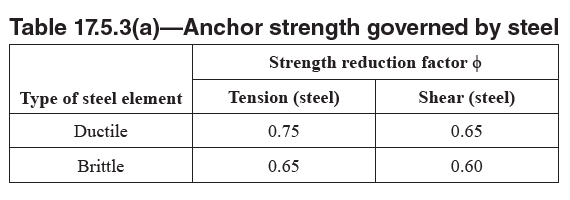
후설치앵커의 강도감소계수는 ACI 355.2에 따른 제품 평가 시험으로부터 결정된 앵커의 범주에 따라서 달라진다.
앵커 설치 시 비틀림 가력, 천공 구멍의 크기, 앵커 설치에 사용된 에너지 수준, 그리고 균열 콘크리트에 사용이 허가된 앵커의 경우 확대된 균열 폭 등을 고려하여 다음과 같은 세 가지 범주로 구분한다.
범주1 - 낮은 설치 민감도와 높은 신뢰성
범주2 - 중간설치 민감도와 중간 신뢰성
범주3 - 높은 설치 민감도와 낮은 신뢰성
서로 다른 기계적 후설치앵커는 각기 다른 법주에 포함되기 때문에 ACI 355.2에 따른 시험으로부터 결정된 제품의 데이터 표를 참조하여야 한다. 다만, 전단을 받는 앵커의 성능은 설치 오차나 허용량에 민감한 편이 아니어서 범주를 고려하지 않아도 된다.
ACI355.2
CHAPTER 10—ESTABLISHING ANCHOR CATEGORIES
10.1 For each combination of anchor diameter and embedment depth, compute the ratio of the characteristic capacity Nb,r in each reliability test to the characteristic tension capacity Nb,o in the corresponding reference test.
The corresponding reference test shall have the same concrete strength range and crack width. Determine the characteristic capacities in accordance with Appendix A2.
The K value used in calculating the characteristic capacity in each reliability test and in the corresponding reference test shall be the K value associated with the reliability test or reference test and the number of respective replicates.
When the reference capacity is associated with tests in which the concrete breakout failure mode predominates, Nb,o shall be permitted to be calculated according to ACI 318, Appendix D, Eq. (D-7), using the effectiveness factor k determined in accordance with 7.3.1.
Using the smallest ratio of Nb,r /Nb,o from all reliability tests, establish the anchor category from Table 10.1.
For each diameter, report a single category that represents the lowest category determined by the tests.
10.2 It shall be permitted to evaluate the ratio Nb,r/Nb,o on the basis of mean test results provided that: 1) the difference in the number of replicates in each test series is not greater than five; and 2) the coefficient of variation associated with the test results in each of the reliability test series is less than or equal to the coefficient of variation associated with the corresponding reference tests, or less than or equal to 10%.
When the reference capacity is associated with tests in which the concrete breakout failure mode predominated, Nb,o shall be permitted to be calculated according to ACI 318, Appendix D, Eq. (D-7), using the effectiveness factor k determined in accordance with 7.3.1, multiplied by a factor 1/0.75.
Table 10.1—Establishment of anchor categories

ACI318-19


Commentary
The ϕ-factors for anchor strength governed by concrete breakout, bond, and side-face blowout in Table 17.5.3(b) are separated into two groups based on the presence or absence of supplementary reinforcement. The supplementary reinforcement classifications of this table replace the “Condition A” and “Condition B” designations in previous Codes.
Applications with supplementary reinforcement provide more deformation capacity, permitting the ϕ-actors to be increased. An explicit design of supplementary reinforcement for anchor-related forces is not required; however, the arrangement of supplementary reinforcement should generally conform to that of the anchor reinforcement shown in Fig. R17.5.2.1(a) and R17.5.2.1(b)(i) and (ii). Unlike anchor reinforcement, full development of supplementary reinforcement beyond the assumed breakout failure plane is not required.
For concrete breakout in shear for all anchor types and for brittle concrete failure modes for cast-in anchors, the basic strength reduction factor for brittle concrete failures (ϕ = 0.70) was chosen based on results of probabilistic studies.
While this factor is greater than the strength reduction factor of structural plain concrete (ϕ = 0.60), the nominal resistance expressions used in this chapter and in the test requirements are based on the 5 percent fractiles; therefore, ϕ = 0.60 would be overly conservative. Comparison with other design procedures and probabilistic studies (Farrow and Klingner 1995) indicated that the choice of ϕ = 0.70 is justified. For the same cases with supplementary reinforcement, the value of ϕ = 0.75 is compatible with the level of safety for shear failures in concrete beams, and has been recommended in the PCI Design Handbook (MNL 120) and by ACI 349M.
Tests included in ACI 355.2 and ACI 355.4M to assess sensitivity to installation procedures determine the Anchor Categories as given in Table 17.5.3(b) for proprietary postinstalled expansion, screw, undercut, and adhesive anchors.
ACI 355.2 tests for installation sensitivity measure effects of variability in anchor torque during installation, tolerance on drilled hole size, and energy level used in setting anchors; for expansion, screw, and undercut anchors intended for use in cracked concrete, increased crack widths are considered. ACI 355.4M tests for installation sensitivity assess the influence of adhesive mixing and the influence of hole cleaning in dry, saturated, and water-filled/underwater bore holes.


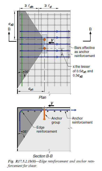
표 17.5.3(b)의 콘크리트 파단, 본드 및 측면 파열에 의해 좌우되는 앵커 강도에 대한 ϕ-계수는 보충 철근의 유무에 따라 두 그룹으로 구분됩니다. 이 표의 보충 보강 분류는 이전 코드의 "조건 A" 및 "조건 B" 지정을 대체합니다.
보충 보강이 있는 애플리케이션은 더 많은 변형 용량을 제공하여 ϕ 계수를 증가시킬 수 있습니다. 앵커 관련 힘에 대한 보충 보강의 명시적인 설계는 필요하지 않지만, 보충 보강의 배치는 일반적으로 그림 R17.5.2.1(a) 및 R17.5.2.1(b)(i) 및 (ii)에 표시된 앵커 보강의 배치와 일치해야 합니다. 앵커 보강과 달리, 가정된 파괴 파괴면을 넘어서는 보충 보강의 완전한 개발은 필요하지 않습니다.
모든 앵커 유형에 대한 전단 콘크리트 파괴와 타설 앵커의 취성 콘크리트 파괴 모드에 대해서는 확률론적 연구 결과를 바탕으로 취성 콘크리트 파괴에 대한 기본 강도 감소 계수(ϕ = 0.70)를 선택했습니다.
이 계수는 구조용 일반 콘크리트의 강도 감소 계수(ϕ = 0.60)보다 크지만, 이 장과 테스트 요구사항에서 사용된 공칭 저항 표현은 5% 파괴율을 기준으로 하므로 ϕ = 0.60은 지나치게 보수적인 수치일 수 있습니다. 다른 설계 절차 및 확률론적 연구(Farrow and Klingner 1995)와 비교한 결과 ϕ = 0.70의 선택이 정당하다는 것을 알 수 있습니다. 보강 철근이 있는 동일한 경우, ϕ = 0.75의 값은 콘크리트 보의 전단 파괴에 대한 안전 수준과 호환되며 PCI 설계 핸드북(MNL 120) 및 ACI 349M에서 권장하고 있습니다.
설치 절차에 대한 민감도를 평가하기 위해 ACI 355.2 및 ACI 355.4M에 포함된 테스트는 독점적인 사후 설치 확장, 나사, 언더컷 및 접착 앵커에 대해 표 17.5.3(b)에 명시된 대로 앵커 카테고리를 결정합니다.
설치 민감도에 대한 ACI 355.2 시험은 설치 중 앵커 토크의 변동성, 드릴 구멍 크기의 공차 및 앵커 설치에 사용되는 에너지 레벨의 영향을 측정하며, 균열 콘크리트에 사용하기 위한 익스팬션, 나사 및 언더컷 앵커의 경우 균열 폭의 증가를 고려합니다. 설치 민감도에 대한 ACI 355.4M 테스트는 접착제 혼합의 영향과 건조, 포화 및 물로 채워진/수중 보어 홀에서 홀 청소의 영향을 평가합니다.


최근댓글